АвтоАвтоматизацияАрхитектураАстрономияАудитБиологияБухгалтерияВоенное делоГенетикаГеографияГеологияГосударствоДомДругоеЖурналистика и СМИИзобретательствоИностранные языкиИнформатикаИскусствоИсторияКомпьютерыКулинарияКультураЛексикологияЛитератураЛогикаМаркетингМатематикаМашиностроениеМедицинаМенеджментМеталлы и СваркаМеханикаМузыкаНаселениеОбразованиеОхрана безопасности жизниОхрана ТрудаПедагогикаПолитикаПравоПриборостроениеПрограммированиеПроизводствоПромышленностьПсихологияРадиоРегилияСвязьСоциологияСпортСтандартизацияСтроительствоТехнологииТорговляТуризмФизикаФизиологияФилософияФинансыХимияХозяйствоЦеннообразованиеЧерчениеЭкологияЭконометрикаЭкономикаЭлектроникаЮриспунденкция
Electromechanical Transducer
|
Читайте также: |
§ A device which converts electrical energy or signals into mechanical energy or signals. For instance, an electric motor.
§ A device which converts mechanical energy or signals into electrical energy or signals. For example, an electric generator.
Circuit measurement is used to monitor the operation of an electrical or electronic device, or to determine the reason a device is not operating properly. Since electricity is invisible, you must use some sort of device to determine what is happening in an electrical circuit. Various devices called test equipment are used to measure electrical quantities. The most common types of test equipment use some kind of metering device.
In 1557, the Welshman Robert Recorde remarked that no two things could be more alike (i.e., more equivalent), than parallel lines and thus was born the equal sign, as in 3 + 4 = 7. Equation (1) is the familiar Rasch model for dichotomous data, which sets a measurement outcome (raw score) equal to a sum of modeled probabilities. The measurement outcome is the dependent variable and the measure (e.g., person parameter, b) and instrument (e.g., item parameters di's) are independent variables. The measurement outcome (e.g., count correct on a reading test) is observed, whereas the measure and instrument parameters are not observed but can be estimated from the response data. When a mechanismic interpretation is imposed on the equation, the right-hand side (r.h.s.) variables are presumed to characterize the process that generates the measurement outcome on the left-hand side (l.h.s.). An illustration of how such a mechanism can be exploited is given in Stone (2002). The item map for the Knox cube test analysis had a 1 logit gap. The specification equation was used to build an item that theory asserted would fill in the gap. Subsequent data analysis confirmed the theoretical prediction of the Rasch relationship:
| Raw score = | 
|
Electric Circuit. We all know that electricity is a form of energy and the energy of electricity is being utilized by different electrical appliance to do the work. A specific type of network or interconnection is required to exploit the electrical energy and to make the electrical appliance to work. The specific inter connection or network of electrical supply source and electrical appliance is know as “ Electric Circuit”.
The electric circuit can be defined as a specific networking or combination of
1. Supply source
2. Wires
3. Electrical Load or appliance and
4. Controller Circuit (Switch etc.)
Measuring instruments are classified according to both the quantity measured by the instrument and the principle of operation. Three general principles of operation are available:
(i) electromagnetic, which utilizes the magnetic effects of electric currents;
(ii) electrostatic, which utilizes the forces between electrically-charged conductors;
(iii) electro-thermic, which utilizes the heating effect.
Electric measuring instruments and meters are used to indicate directly the value of current, voltage, power or energy. In this lesson, we will consider an electromechanical meter (input is as an electrical signal results mechanical force or torque as an output) that can be connected with additional suitable components in order to act as an ammeters and a voltmeter. The most common analogue instrument or meter is the permanent magnet moving coil instrument and it is used for measuring a dc current or voltage of a electric circuit. On the other hand, the indications of alternating current ammeters and voltmeters must represent the RMS values of the current, or voltage, respectively, applied to the instrument.
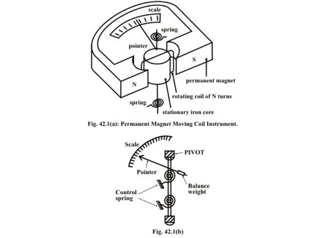
The general theory of moving-coil instruments may be dealt with considering a rectangular coil of N turns, free to rotate about a vertical axis. Fig. 42.1(a) shows the basic construction of a PMMC instrument. A moving coil instrument consists basically of a permanent magnet to provide a magnetic field and a small lightweight coil is wound on a rectangular soft iron core that is free to rotate around Version 2 EE IIT, Kharagpur its vertical axis. When a current is passed through the coil windings, a torque is developed on the coil by the interaction of the magnetic field and the field set up by the current in the coil. The aluminum pointer attached to rotating coil and the pointer moves around the calibrated scale indicates the deflection of the coil. To reduce parallax error a mirror is usually placed along with the scale. A balance weight is also attached to the pointer to counteract its weight (see Fig. 42.1(b)). To use PMMC device as a meter, two problems must be solved. First, a way must be found to return the coil to its original
position when there is no current through the coil. Second, a method is needed to indicate the amount of coil movement. The first problem is solved by the use of hairsprings attached to each end of the coil as shown in Fig. 42.1(a). These hairsprings are not only supplying a restoring torque but also provide an electric connection to the rotating coil. With the use of hairsprings, the coil will return to its initial position when no current is flowing though the coil. The springs will also resist the movement of coil when there is current through coil. When the developing force between the magnetic fields (from permanent magnet and electro magnet) is exactly equal to the force of the springs, the coil rotation will stop. The coil set up is supported on jeweled bearingsin order to achieve free movement. Two other features are considered to increase the accuracy and efficiency of this meter movement. First, an iron core is placed inside the coil to concentrate the magnetic fields. Second, the curved pole faces ensure the turning force on the coil increases as the current increases.
It is assumed that the coil sides are situated in a uniform radial magnetic field of flux density 2 B wb m/, let the length of a coil side (within the magnetic field) be l (meter), and the distance from each coil side to the axis be r (meter).
Поиск по сайту: