АвтоАвтоматизацияАрхитектураАстрономияАудитБиологияБухгалтерияВоенное делоГенетикаГеографияГеологияГосударствоДомДругоеЖурналистика и СМИИзобретательствоИностранные языкиИнформатикаИскусствоИсторияКомпьютерыКулинарияКультураЛексикологияЛитератураЛогикаМаркетингМатематикаМашиностроениеМедицинаМенеджментМеталлы и СваркаМеханикаМузыкаНаселениеОбразованиеОхрана безопасности жизниОхрана ТрудаПедагогикаПолитикаПравоПриборостроениеПрограммированиеПроизводствоПромышленностьПсихологияРадиоРегилияСвязьСоциологияСпортСтандартизацияСтроительствоТехнологииТорговляТуризмФизикаФизиологияФилософияФинансыХимияХозяйствоЦеннообразованиеЧерчениеЭкологияЭконометрикаЭкономикаЭлектроникаЮриспунденкция
Internal Resistance
|
Читайте также: |
Slobodov Aleksandr
Introduction
One of the interesting ideas that might occur to you in thinking about circuits is that if a battery were hooked up to a conductor with zero resistance, there would be no limit on the amount of current flowing through the resistor.
An interesting effect of the internal resistance is that it causes the charges in the current to lose some of their voltage before they even make it out of the battery. This means the voltage supplied by the battery is actually less than it theoretically should be. We call the theoretical voltage supplied by a battery its electromotive force (or EMF for short) and the actual voltage that we measure at its electrodes is called its terminal voltage. The internal resistance of a battery depends on the materials from which the battery is made and the condition it is in. As batteries get older their internal resistance increases, which means more of the EMF is used up getting through the battery and less it available as terminal voltage to power a circuit.
To analyze the effect of the internal resistance, we treat it like it is in series with the rest of the load – in this case a single variable resistor – called a potentiometer or a rheostat.
Theory
The occurrence of the potential difference at the poles of the source of any results from the separation therein positive and negative charges. This division is due to the work done by external forces. When you move the electric charges of the DC party forces acting within the current sources, perform work. Physical quantity, equal to the ratio of work FTS external forces when moving charge q inside the power supply to the magnitude of this charge is called electromotive force source (EMF):

EMF is determined by the work done by external forces when moving a single positive charge. Electromotive force, as well as the potential difference, measured in volts [V].
To measure the EMF source, it is necessary to attach the voltmeter open circuit. The power source is a conductor, and always has some resistance, so current releases it warm. This resistance is called the internal resistance of the source and indicate r.
If the circuit is open, the work of external forces is transformed into potential energy of the power source. Closed circuit this potential energy is expended to work on moving charges in an external circuit with resistance R and the inner part of the circuit with a resistance r, i.e., ε = IR + Ir.
If the chain is composed of the outer part of the resistance R and the internal resistance r, then, according to the law of conservation of energy, the source of EMF is equal to the amount of stress on the external and internal parts of the circuit, as when moving along a closed circuit charge resets where IR - the voltage on the external portion of the chain ε = IR + Ir, and Ir - voltage at the inner portion of the circuit.
Thus, for sub circuit comprising EMF:

Most sources of electrical energy for the interconnected supply chain. Connecting sources in the battery can be serial and parallel.
Apparatus
2 x multimeters (use one as an ammeter and one as a voltmeter)
10 x resistors of different sizes (10 to 200Ω)
5 x 4 mm Leads
1 x C battery
Method
Calculate the resistance of resistors, by using resister color chart.
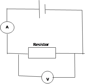
Arrange all of them increasing size. Connect multimeters as shown on this diagram.
Begin taking measurements from the lowest resistor in the circuit and record the potential difference (V) and the current (I). Using Ohm’s law find the potential difference (V) and current (A). Fill the table with this results. Graph the results. The circuit shouldn’t be connected to the battery, when the resistance is low, in this time, the current is high, because this will run the cell down very quickly. The size of resistors should be increased by any new measurement. Measurements should be taken from multimeter (voltage and current) for a minimum of ten resistors.
When all measurements are taken, everything should be recorded from the highest resistor to the lowest.
Results
The resistance of all resistors, given, are given in the first column and arranged from the lowest to the highest. Resistance are given in Ohm (Ω). Second section (Potential Difference (V)) in Table 1 is divided into 3 columns: Resistor increasing, Resistor decreasing and Average result of two previous columns. In Resistor increasing column measurements were taken from the lowest resistance resistor to the highest resistance resistor. In Resistor decreasing, potential difference (V) were recorded from the highest resistance resistor to the lowest resistance resistor. Average result is the recording from Resistor increasing multiplied by Resistor decreasing and divided by 2. And the third section Current (A) is divided into 3 sections: Resistor increasing, Resistor decreasing and average result of previous two measurements. Resistor increasing, Resistor decreasing and Average were recorded as in Potential difference (V) but results were taken from ammeter.
On Figure 1 we scratch graph  . V is recordings from Potential resistance (V) sector from Average results. I is recordings from Current (A) from Average results. Scratched the graph we have the equation of line. The equation is
  . The gradient is the seeking resistance. We take absolute result of the gradient and get the resistance which equals 2,395 Ω.
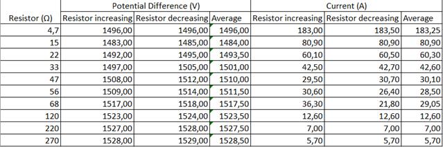
Table 1

Figure 1
Discussion
Conclusion
Поиск по сайту: