АвтоАвтоматизацияАрхитектураАстрономияАудитБиологияБухгалтерияВоенное делоГенетикаГеографияГеологияГосударствоДомДругоеЖурналистика и СМИИзобретательствоИностранные языкиИнформатикаИскусствоИсторияКомпьютерыКулинарияКультураЛексикологияЛитератураЛогикаМаркетингМатематикаМашиностроениеМедицинаМенеджментМеталлы и СваркаМеханикаМузыкаНаселениеОбразованиеОхрана безопасности жизниОхрана ТрудаПедагогикаПолитикаПравоПриборостроениеПрограммированиеПроизводствоПромышленностьПсихологияРадиоРегилияСвязьСоциологияСпортСтандартизацияСтроительствоТехнологииТорговляТуризмФизикаФизиологияФилософияФинансыХимияХозяйствоЦеннообразованиеЧерчениеЭкологияЭконометрикаЭкономикаЭлектроникаЮриспунденкция
Railway Overhead Line (Catenary)
|
Читайте также: |
202. 
203.
204. 
205. Contact wire cross section
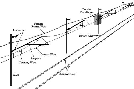
206. Power supply of electric locomotives is made with the help of wires with current over the track. Overhead line systems are called "catenary" from the Latin word “catena” meaning “chain”. Catenary is the curve formed by the supporting cable with a complex geometry, nowadays usually designed by computer. The wire must be able to carry the current (several thousand amperes), remain in line with the route, withstand wind (can reach 200 km/h), extreme cold and heat and other hostile weather conditions. The contact wire has to be held in tension horizontally and pulled laterally to make curves in the track. The contact wire tension will be in the region of 2 tonnes. The wire length is usually between 1000 and 1500 metres long, depending on the temperature ranges. The wire has zig-zags relative to the centre line of the track to make even the train's pantograph wear.
207. The contact wire is grooved. A clip is fixed on the top side. The clip is used to attach the dropper wire. The tension of the wire is maintained by weights suspended at each end of its length. Each length is overlapped by its neighbour to ensure a smooth passage for the pantograph. Incorrect tension, combined with the wrong speed of a train, will cause the pantograph head to start bouncing. An electric arc occurs with each bounce and a pantograph and wire will soon both become worn through under such conditions.
208. More than one pantograph on a train can cause a similar problem when the leading pantograph head makes a wave in the wire and the rear pantograph can’t stay in contact. A waving wire will cause another problem. It can cause the dropper wires, from which the contact wire is hung, to form little loops. The contact wire then becomes too high and increases the poor contact.
209. AC overhead sections are usually much longer than DC overhead sections. Each subsection is isolated from its neighbour by a section insulator in the overhead contact. The subsections can be joined through special high speed section switches.
210. To reduce the arcing at a neutral section in the overhead catenary, some systems use track magnets to automatically switch off the power on the train on the approach to the neutral section. A second set of magnets restores the power immediately after the neutral section has been passed.
211.
212. 
213.
214.
215.
216.
217.
218.
219.
220.
221.
222.
223.
224.
225.
226.
227. 
228. The photo shows a set of track magnets.
Поиск по сайту: